How to change an actuation valve on a Coolubricator™ or Serv-O-Spray™ system.
Coolubricator™and Serv-O-Spray™systems can be configured and operated in many different ways. Some common actuation methods for these types of systems are electrical solenoid valves, air pilot valves, and manual slide valves. This document will outline the basic steps to replace either a solenoid or air pilot valve on these systems.
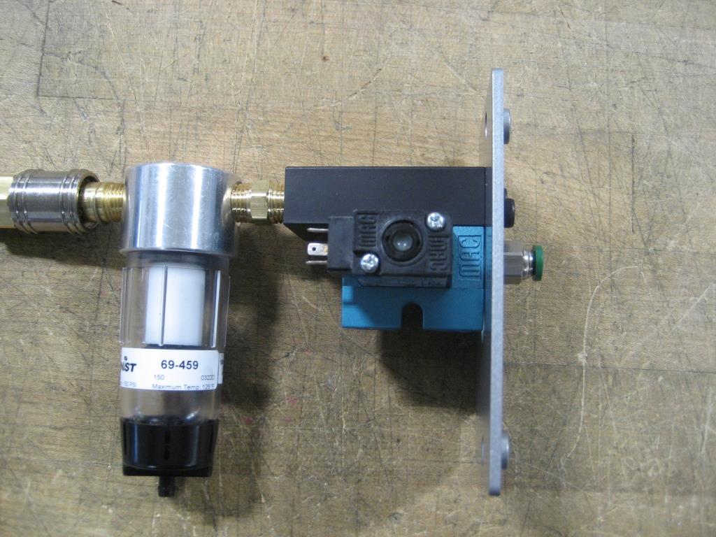
Three common system valve configurations are internally mounted solenoid valve, externally mounted solenoid valve, and air pilot valve. Although your specific system or valve may look slightly different, the steps shown below are applicable to all these standard systems.
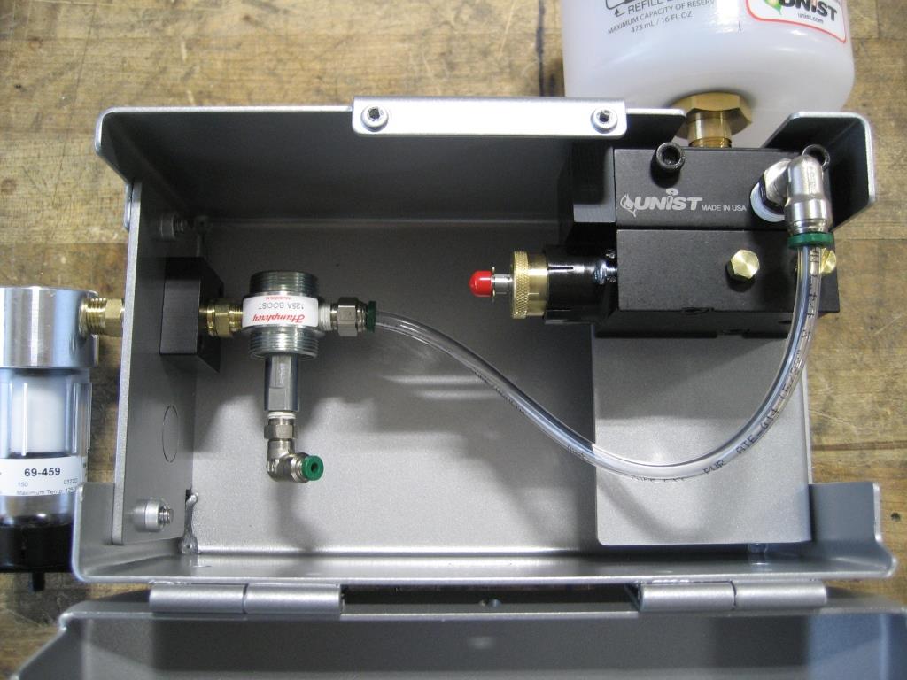
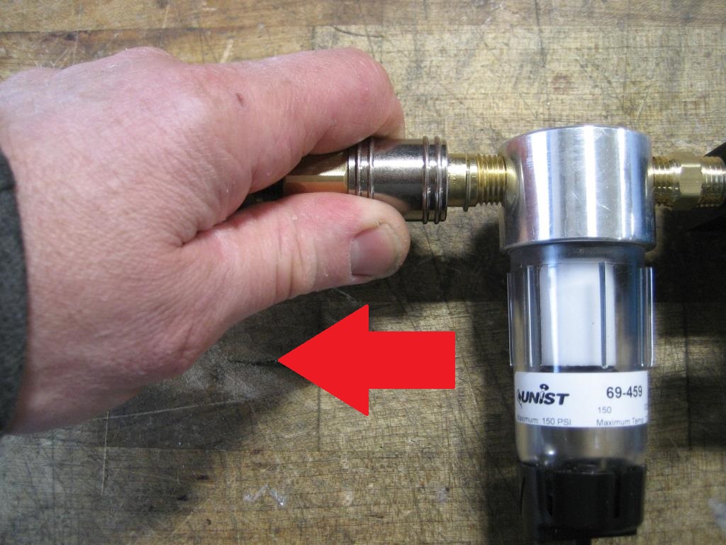
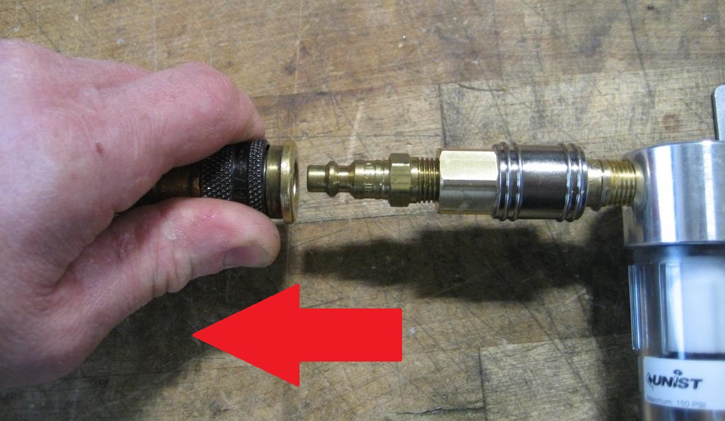
First begin closing the slide valve (if equipped) and disconnecting the pressurized air line on the system.
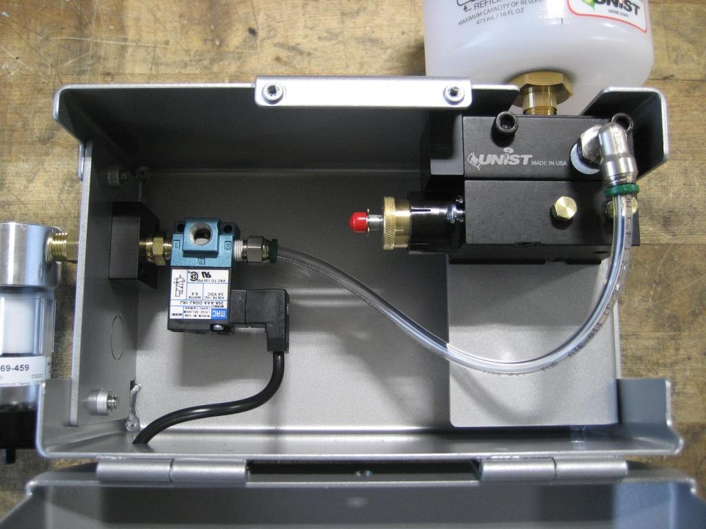
Internally Mounted Valves
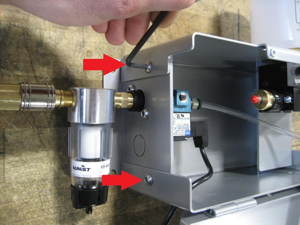
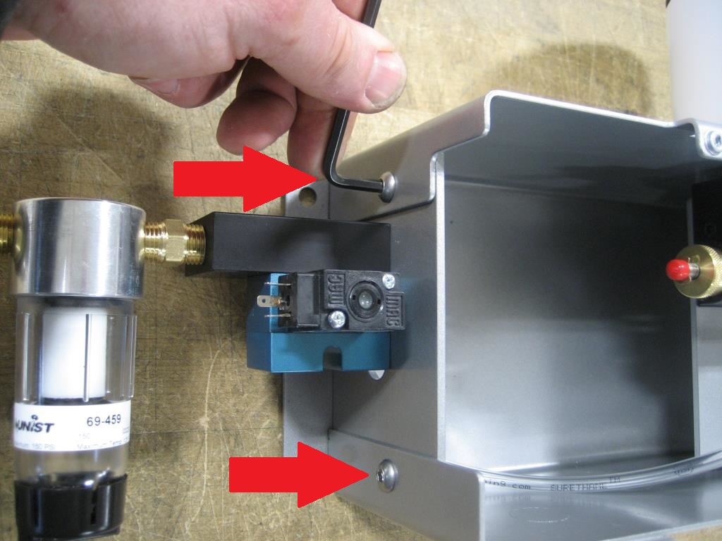
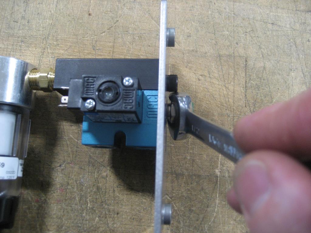
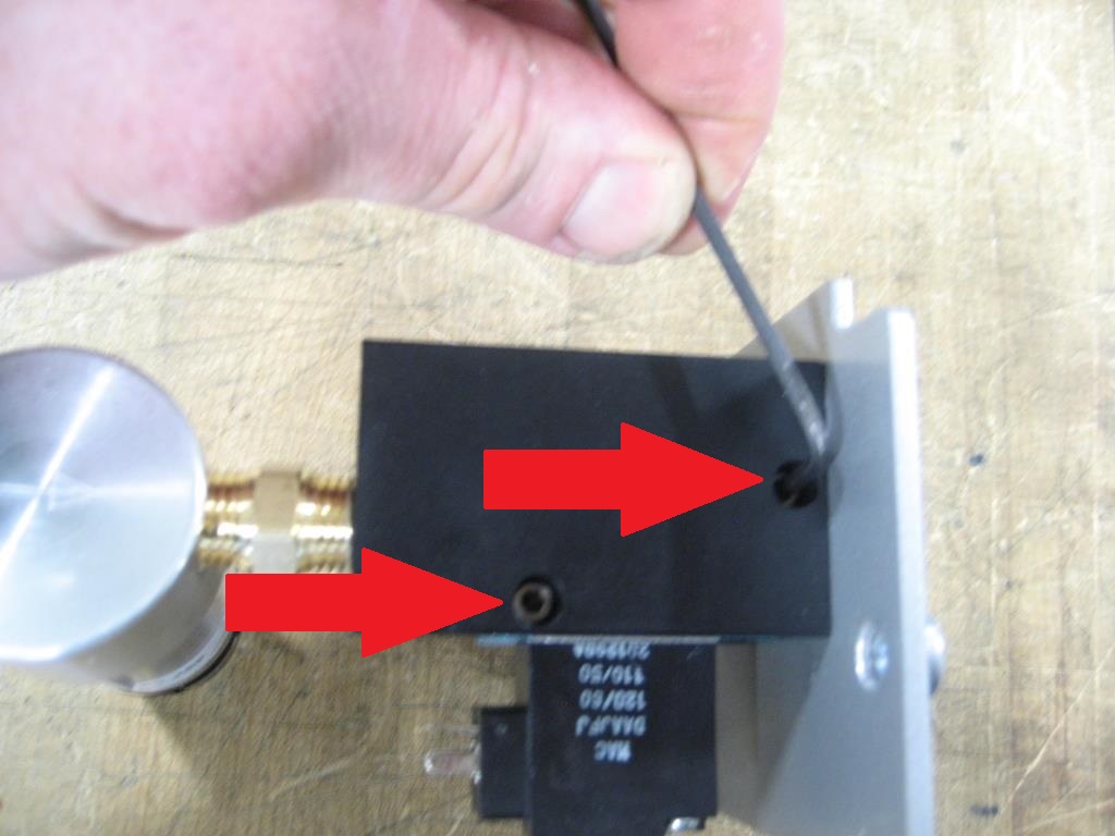
For internally mounted and air pilot valves, disconnect the air line from the fitting on the pump stack and remove the two screws attaching the side plate to the main rear enclosure.
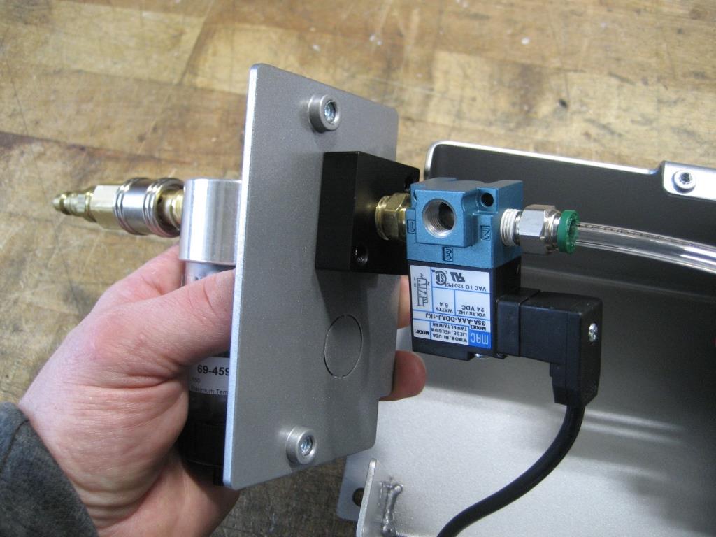
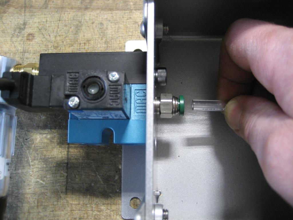
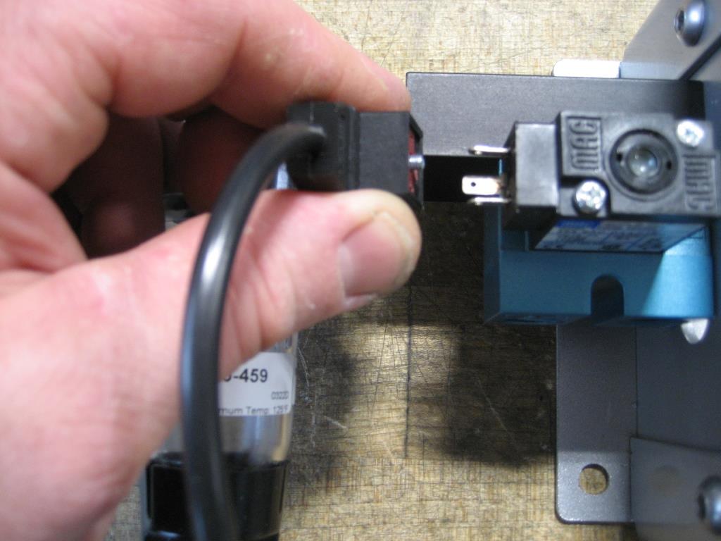
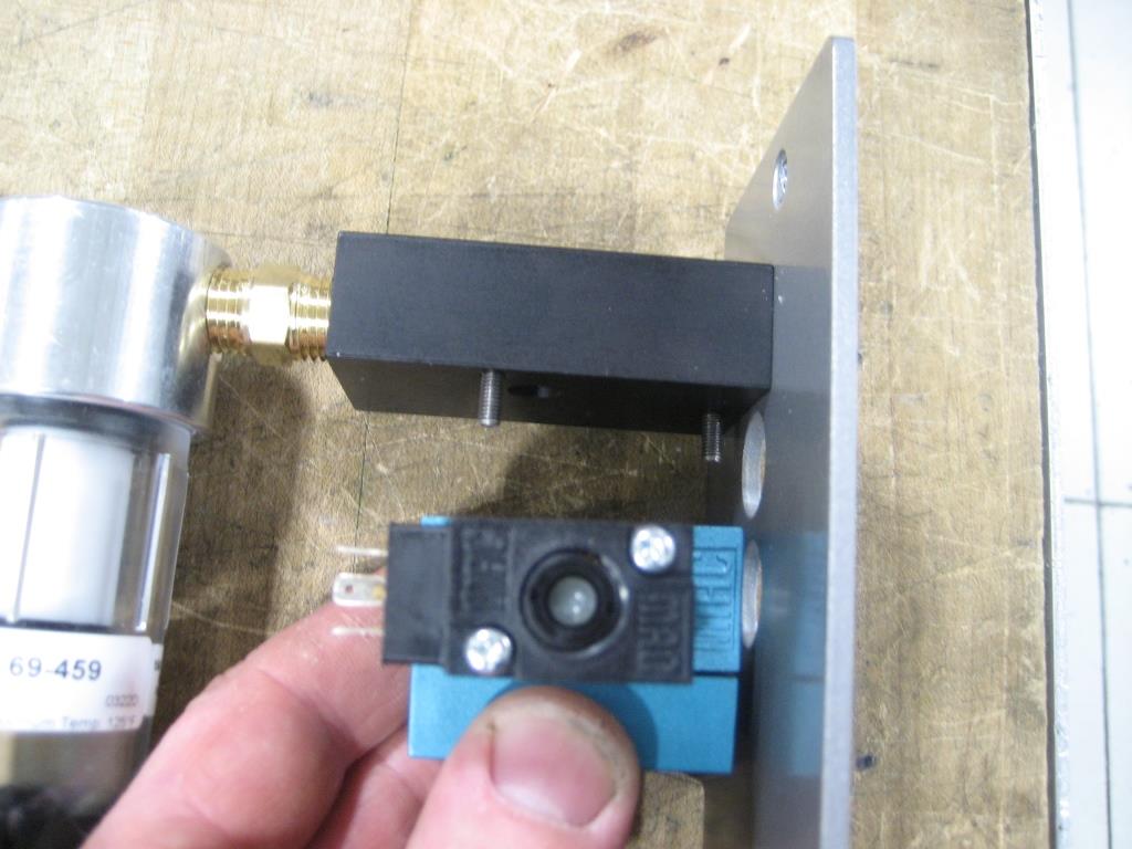
Remove the side panel sub-assembly from the enclosure, disconnect the DIN connector (for solenoid valves), and unscrew the valve from the fitting.
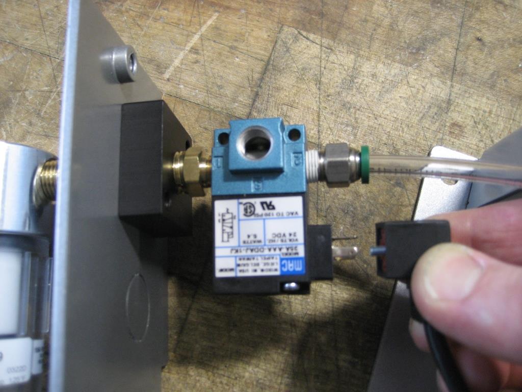
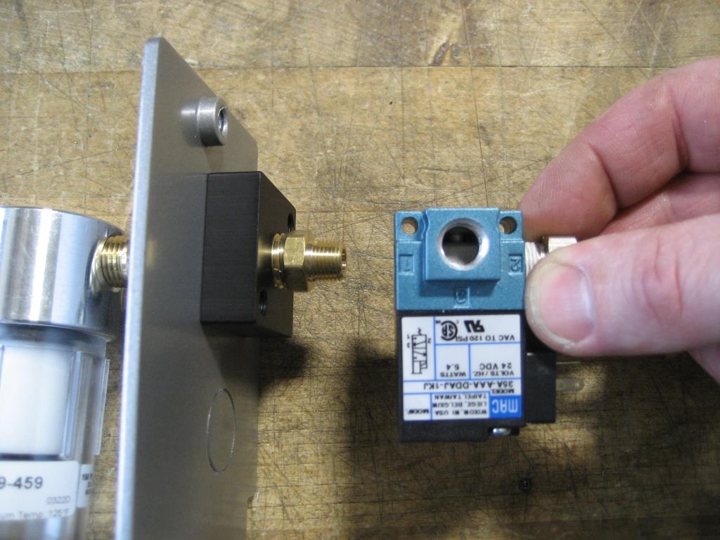
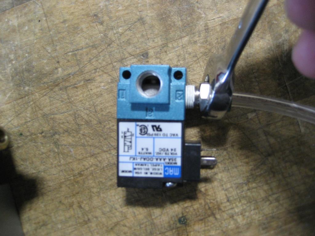
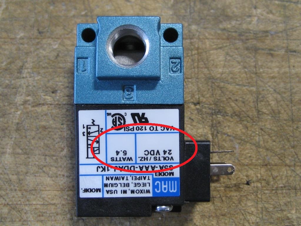
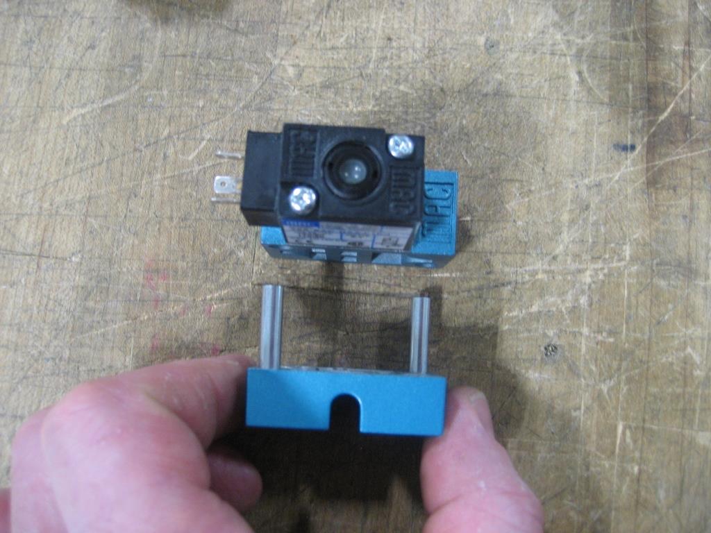
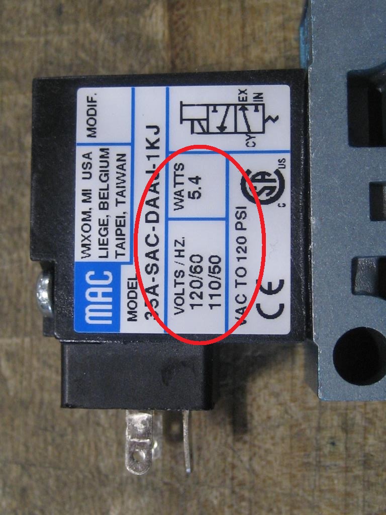
Remove any fittings from the old valve to transfer onto the replacement valve. For solenoid valves, confirm that the voltage noted on the coil matches between the old and replacement valves.
Assembly is the reverse of disassembly.
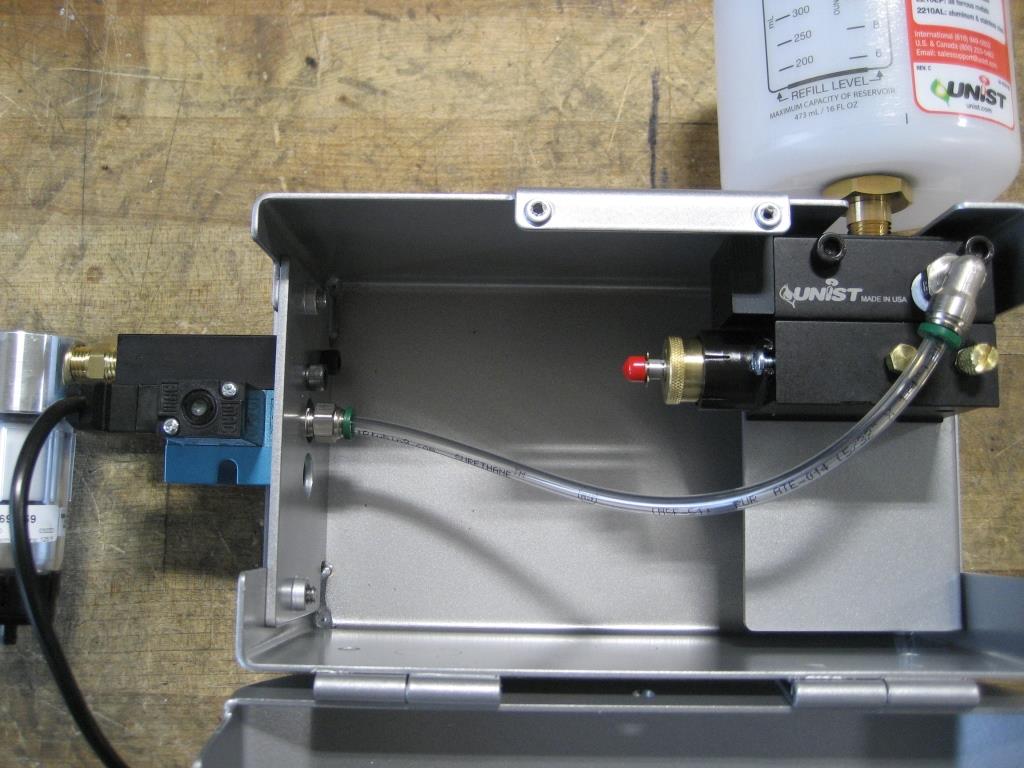
Externally Mounted Valves
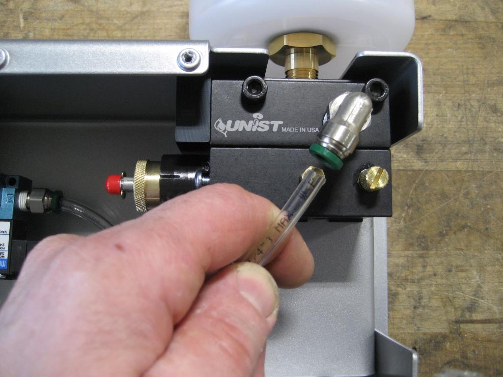
For externally mounted solenoid valves, disconnect the air line(s) from the fitting(s) on the valve and disconnect the DIN connector(s) from the valve(s).
Remove the two screws attaching the side plate to the main rear enclosure and remove the sub-assembly. Remove any fittings on the valve being replaced (note, a socket and ratchet may be required to remove fittings from a valve stack with multiple valves in it.
Use a 2.5mm hex key to remove the two valve stack retaining screws from the top of the manifold block, disassemble the valve stack and remove the old valve.
Ensure that the voltage noted on the coil matches between the old and replacement valves.
Assembly is the reverse of disassembly.