Knowledge Base By Product:
Can't find the answer? We'd love to help!
Related video:

Unist - How To: Set Up Your Coolubricator™
Unist Home | Technical Knowledge Base | | Machining & Cutting | Installation | How do I set my system up?
How do I set my system up?
Coolubricator™ or Serv-O-Spray™System™
2021-03-02
By Kevin
There are many different variations of Coolubricator™ and Serv-O-Spray™systems, but their basic construction and set up are all very similar.
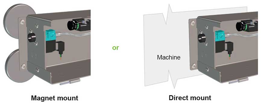
- Mounting: Mount the system in a safe place where it is easily accessible for connections, adjustments, and adding fluid. Do not mount the system so high that it is difficult to add fluid to the reservoir if it is so equipped. Systems in a steel enclosure will have four holes that the system can be mounted by. An easier option is to attach magnets to the enclosure and use the magnets to attach the enclosure to the side of a machine or something similar. Appropriate magnets and mounting hardware are available from Unist.
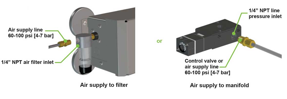
- Compressed air source: The system will require a minimum of 60 psi connected to it to operate properly. 80 – 100 psi is recommended. Typically the compressed air will connect to an air filter on the left side of the enclosure or to a valve mounted directly on the top manifold block for systems not mounted in a full enclosure.
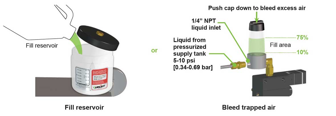
- Fluid: Systems can receive fluid from a gravity feed reservoir (typically mounted directly to the top manifold block) or from a pressurized fluid source. If the system is to be fed from a pressurized fluid source then it will need to be equipped with an air trap to ensure consistent fluid delivery to the pump(s). Either fill the gravity feed reservoir with the appropriate fluid or connect the pressurized fluid source to the air trap and depress the black cap on the air trap to bleed excess air until it is approximately 75% full of fluid.
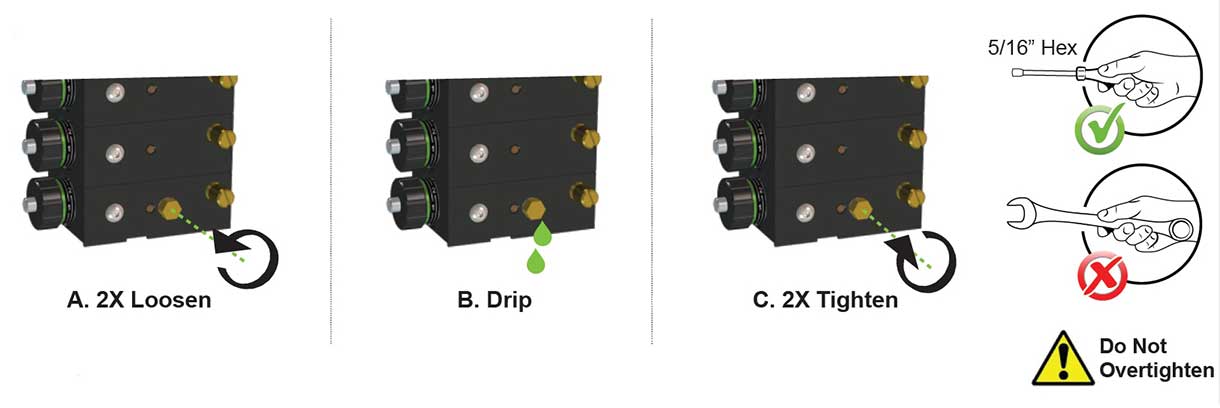
- Bleed pump(s): Once the system has a fluid source it will be necessary to get that fluid into the pump stack so the pumps can begin to pump it. Without bleeding the pump(s) there will be air trapped in the pump(s) and it will be difficult to get fluid output from the system. A brass bleed screw is present on the front face of the bottom pump in the stack that can be used to bleed air and introduce fluid into the pump stack. The screw has a 5/16” (8mm) hex. The screw only needs to be loosened approximately two turns until fluid drains from the plug. Once fluid is present at the screw it can be retightened. DO NOT overtighten the bleed screw or it may break off in the block.
- Pump output: Once the pumps have fluid in them, they should begin pumping. Open the main air control valve to introduce pressurized air to the pump stack and begin cycling the pumps. It is normally advantageous to run the pumps at a fast cycle rate (approximately 100 cycles per minute) initially to aid in getting them to start pumping fluid. Controls will vary depending on if the system is a Coolubricator™ or Serv-O-Spray. A Coolubricator™ will have a pulse generator which can be used to control the pump cycle rate while a Serv-O-Spray™will have an air control valve that will have to be toggled on/off to cycle the pump(s). There are instances where it can be difficult to get a pump to begin pumping fluid if an air pocket will not bleed from the pump. It can be helpful to open the bleed screw to allow additional fluid to run through the pump stack. It can also help to vary the cycle rate fast-slow-fast to aid in getting any trapped air out of the pump. It is always recommended to bleed pumps while they are set to full stroke.
- Priming the Outlet Hose(s): Once it has been established that the pumps are pumping fluid then it will be necessary to prime the outlet hoses with fluid. This is necessary on coaxial hose output systems to get fluid up to the nozzle tip. There will be no fluid output from the nozzle until the small inner 1/8” diameter hose carrying the fluid from the pump to the nozzle is full of fluid. Run the pumps until all capillary hoses are filled with fluid and output is observed at the nozzle tip (Note: spraying the nozzle onto a piece of cardboard is an easy way to verify that there is fluid output at the nozzle). This step is not necessary for single line systems where the air and fluid are mixed right at the outlet of the pump. In these systems the atomizing air is used to carry the fluid through the hose to the nozzle. If the entire line on these systems is completely filled with fluid, there will be excessive fluid output from the system until the line is cleared. Cycle a pump on a single line system with the air metering screw opened to push fluid to the nozzle until output is observed. Note that the hoses on an oil only pump look similar to a single line output, but they have no air to propel the fluid through the hose. These pumps do need the entire hose filled with fluid before output will be observed from the system.
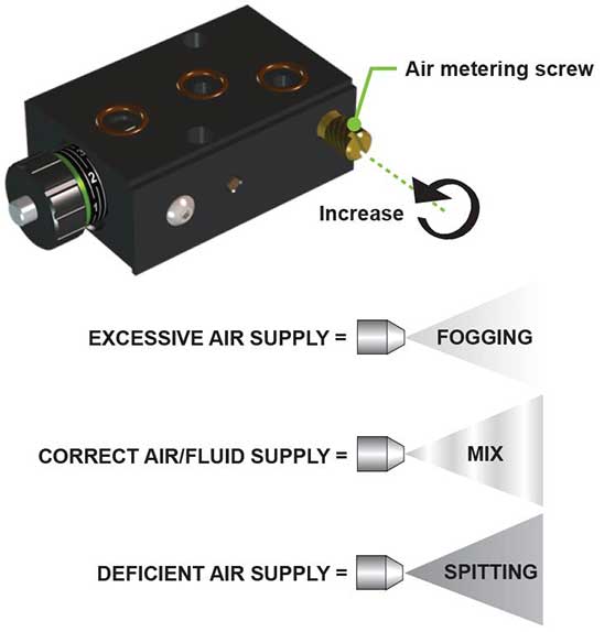
- Air Metering Screw Adjustment (not applicable to oil only pumps): The air metering screw on the pump is used to regulate the air used to atomize the fluid at the nozzle. Many different factors including hose length, nozzle type, fluid viscosity, and application type can affect the optimum air metering screw setting. Generally, there only needs to be enough air flow to properly atomize and push the fluid onto the tool or workpiece. Too little air flow may not properly atomize the fluid and lead to large fluid droplets and inconsistent output. Too much air flow can cause excessive fogging and waste of compressed air. A good starting adjustment for the air metering screw is ½ - ¾ of a turn open from fully closed. Minute adjustments can be made from there until proper operation has been achieved.
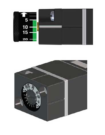
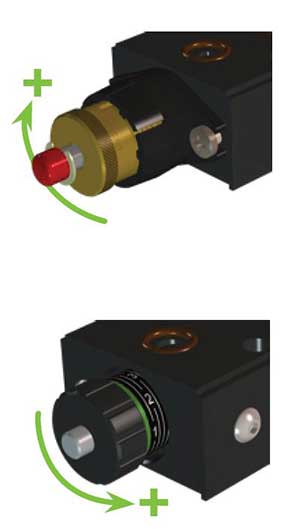
- Pump Cycle Rate and Pump Stroke Adjustment: Like the air metering screw, the ideal pump cycle rate and stroke varies greatly from application to application. The pump cycle rate is recommended as the primary adjustment to either increase or decrease fluid output from the system. A good starting point for a Coolubricator™ system is 10-20 pump cycles per minute. This can be adjusted up by turning the adjustment knob or screw (depending on how the pulse generator is outfitted) counterclockwise or down by turning clockwise until the appropriate cycle rate is attained. The adjustment knob or screw can be turned an infinite number of times, but it only has 360 degrees of adjustment. In other words, if the pulse generator starts at a set point and is rotated 360 degrees it will have gone through its full range of adjustment and return to its original setting. The pump on a Serv-O-Spray™system cycles once every time that the main air control valve on the system is opened. Pumps come from the factory set at full stroke. The stroke can be reduced to tune a system to get optimum and consistent fluid output for a specific application. For instance, if a Coolubricator™ set at 10 cycles per minute at full stroke does not give good consistent fluid output the cycle rate can be increased to 20 cycles per minute while the pump stroke is adjusted to half to achieve the same average fluid output, but yield more consistent output while it is on. On a standard pump, the stroke is increased when the brass adjustment knob is turned clockwise and reduced when the adjustment knob is turned counterclockwise. On an MV pump the stroke is decreased when the black aluminum adjustment knob is turned clockwise and increased when the adjustment knob is turned counterclockwise. It is normally best to keep the stroke adjustment between full and half stroke for optimum and consistent output.
The related video has some excellent information for setting up a Coolubricator™ system.
Additionally, the operator manual for each system has good overall system setup information.
Related video:
Unist - How To: Set Up Your Coolubricator™