Uni-Max Pro Flow Sensor Operation
Uni-Max Pro pump systems use a magnetic sensor to confirm that fluid is being dispensed from the pump. The sensor does not measure flow rate directly; instead, it detects the movement of a spring-loaded magnet inside the pump outlet during each pump stroke. When the pump actuates, fluid pushes the magnet away from its resting position, bringing it within range of the sensor. This causes the sensor output to change state, providing a confirmation signal that fluid has been dispensed. Once fluid stops, the spring returns the magnet to its normal position and the sensor output returns to its resting state.
PNP Sensor Output Wiring
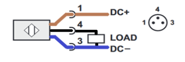
The Uni-Max Pro systems use a PNP sensor with three wires:
- Brown: +VDC supply
- Blue: 0 VDC (common)
- Black: Output signal
Signal Behavior and Monitoring
In the normal (resting) state, the output signal is 0 VDC. When the sensor detects the magnet during a pump stroke, the output switches to the supply voltage, providing a signal that can be monitored by the customer’s control system. The signal can be monitored by a PLC or any other input device compatible with a 5-28VDC input. The signal should be monitored to ensure it goes high within 50ms of the pump stroke. There is typically a 20ms delay between the pump stroke and the signal going high. This monitoring can be used to alert an operator by monitoring both pump actuation and fluid flow, the sensor can help identify two distinct failure modes: (1) the pump is stroking, but fluid is not being dispensed, and (2) the pump is not stroking despite receiving the required actuation signal or air supply.
Fluid Flow Sensor Specifications
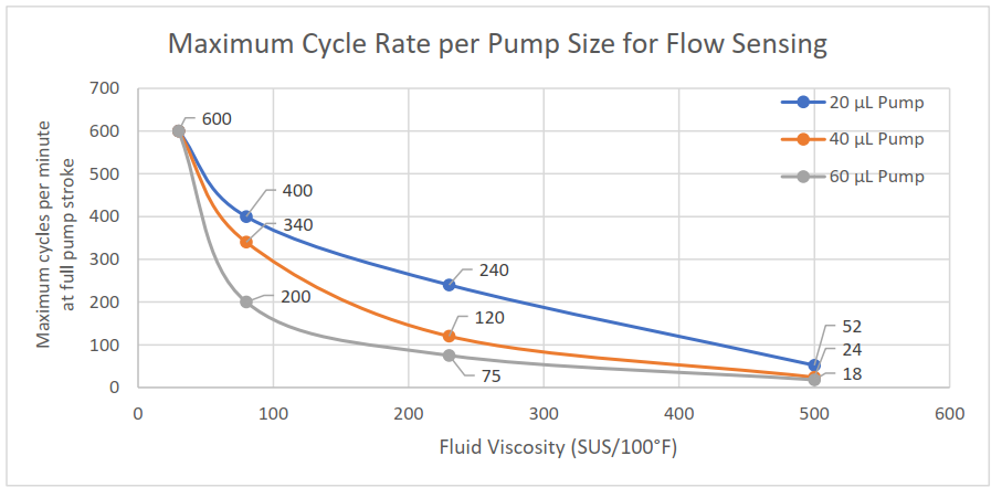
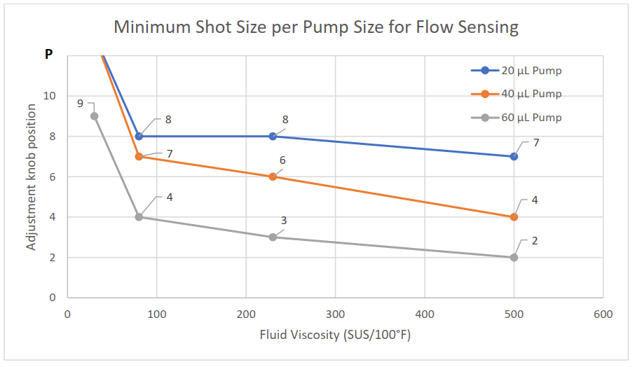
Flow sensors are used to detect fluid output from the pump but have limitations based on the viscosity of the fluid, the amount of fluid dispensed each stroke, and the cycle rate of the pump. For reliable flow sensing, the minimum adjustment knob position must be set according to the viscosity and pump size. Adjustment knob positions lower than the recommended line for the respective pump size and viscosity may cause unreliable flow sensing results.
Thinner fluids require a higher adjustment knob position (larger amount of fluid per stroke) but can run at faster cycle rates. Thicker fluids can tolerate lower adjustment knob positions but have a lower maximum cycle rate.
Refer to the following charts for guidance:
- Minimum Shot Size per Pump Size for Flow Sensing
(Using values below the lines shown may not be reliable for flow sensing with respective fluids)
- Maximum Cycle Rate per Pump Size for Flow Sensing
(Cycle rates above the lines shown may not be reliable for flow sensing with respective fluids)